

Cisco Air Lap1142n E K9 Anleitung
Table of Contents
Access Point Mounting Instructions
Contents
Introduction
Mounting Hardware
Mounting Brackets
Ceiling Grid Clips
Additional Adapters for Aqueduct and Axle Ceiling Track
Mounting an Access Point Below a Suspended Ceiling
Mounting an Access Point on a Hard Ceiling or a Wall
Mounting an Access Bespeak to a Network or Electrical Box
Mounting an Admission Point Above a Suspended Ceiling
Grounding an Admission Indicate
Securing an Access Point
Using a Security Cable
Securing the Access Point to the Mounting Plate
Obtaining Documentation and Submitting a Service Asking
Access Point Mounting Instructions
Published: November viii, 2010
Revised: February 07, 2019
Introduction
These mounting instructions describe the steps for mounting supported Cisco Aironet series access points in several configurations, including on a suspended ceiling, on a hard ceiling or wall, on an electrical or network box, and above a suspended ceiling.
Mounting Hardware
Mounting hardware for admission points consists of brackets, which connect to the bottom of the access point, and ceiling filigree clips, which connect the subclass to a suspended ceiling. The bracket that you lot need depends on the mounting location for the access point. The ceiling grid clip that y'all need depends on the type of suspended ceiling where you need to install the admission indicate. You don't need ceiling grid clips if you are mounting the access indicate to a hard-surface ceiling or a wall.
Mounting Brackets
Two mounting brackets are available:
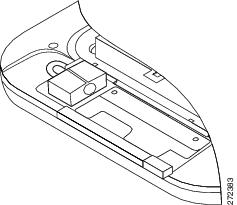
- The low-profile subclass (AIR-AP-Bracket-1), which provides a tight fit betwixt the access point and the ceiling but does not accommodate network/electrical box or wall mounting. Effigy i shows the depression-profile bracket installed on an admission point.
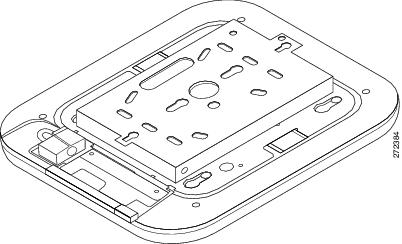
- The universal bracket (AIR-AP-BRACKET-2), which is versatile (it works with electric boxes, can be used for wall mounting, and adapts to ceiling installations) but leaves a larger gap betwixt the mounting surface and the access bespeak than the low-profile subclass. The larger gap is necessary in some locations because it allows infinite for cable routing. Effigy 2 shows the universal subclass installed on an admission point.

Annotation ![]() The AP1130 ships with a specialized subclass. The information presented here on brackets does not utilize to the AP1130.
The AP1130 ships with a specialized subclass. The information presented here on brackets does not utilize to the AP1130.
Figure one Low-Profile Mounting Subclass Installed on an Access Bespeak
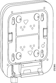
Figure 2 Universal Bracket Installed on an Access Point
Ceiling Grid Clips
You use a ceiling grid clip to mount an access betoken on a suspended ceiling. The ceiling grid clip that you need depends on the ceiling tiles on your ceiling. There are 2 types of ceiling grid clips:
- Ceiling Grid Clip, Recessed (AIR-AP-T-Rails-R)—If your ceiling tiles hang below the ceiling grid, this clip provides the all-time fit between the AP and the ceiling.
- Ceiling Filigree Clip, Flush (AIR-AP-T-RAIL-F)—If your ceiling tiles are flush with the ceiling grid, this clip provides a snug fit between the AP and the ceiling.
Figure 3 shows a ceiling grid clip.
Figure 3 Ceiling Grid Prune
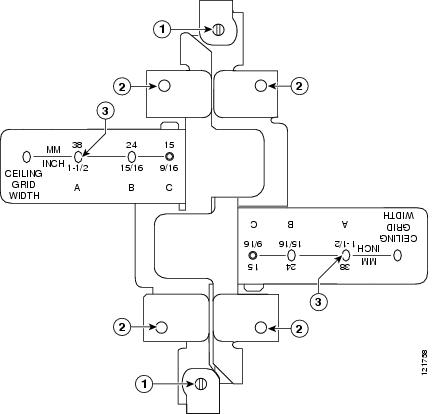
| ane | Locking screws | 3 | T-rail width detents (A, B, or C) |
| 2 | Subclass screw holes | ||
Boosted Adapters for Channel and Axle Ceiling Rails
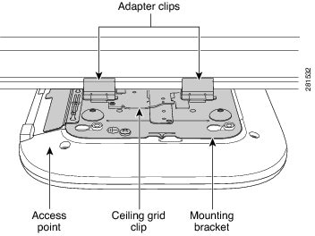
The almost common blazon of ceiling rail (the supports for the ceiling tiles) is the T-track. Y'all can attach a ceiling grid clip straight to a T-rail ceiling rail. However, other types of ceiling rails, such as channel runway and axle track, crave an boosted adapter clip (AIR-CHNL-ADAPTER). You need 2 adapter clips for each access bespeak. Setscrews on the clips hold them securely on the ceiling runway.
Figure 4 shows the three types of ceiling rail: T-runway, channel, and beam. Effigy 5 shows an admission point installed with mounting subclass, ceiling grid prune, and adapter clips.
Figure iv T-Rail, Channel, and Beam Ceiling Runway Types
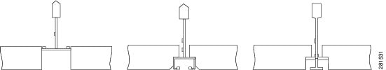
Figure 5 Adapter Clips Installed with Ceiling Filigree Clips
Mounting an Access Point Below a Suspended Ceiling
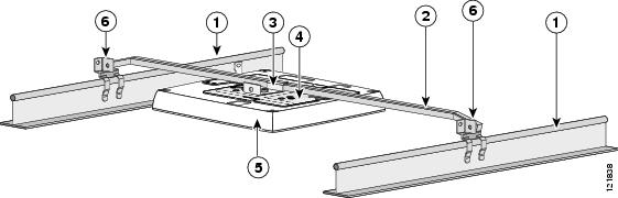
Follow these steps to mount the access point below a standard or recessed suspended ceiling. Figure vi shows an access point mounted on a T-rail ceiling runway using a ceiling grid clip.
Figure 6 Suspended Ceiling Mounting Details
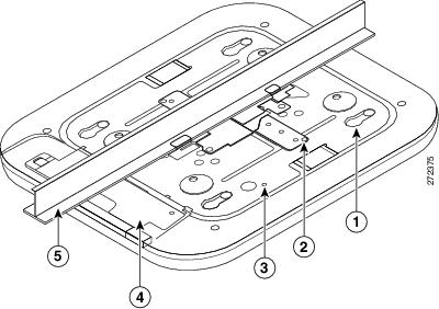
| ane | Access signal mounting keyhole | four | Access point cable access cover |
| 2 | Ceiling grid prune | 5 | Ceiling T-rail |
| 3 | Grounding point | ||
Follow these steps to mountain the admission point below a suspended ceiling.
Stride 1 ![]() Decide where y'all want to mount the access point on your suspended ceiling.
Decide where y'all want to mount the access point on your suspended ceiling.
Footstep 2 ![]() Open the ceiling grid clip completely.
Open the ceiling grid clip completely.
Step three ![]() Place the ceiling grid prune over the T-rail and close it to the appropriate detent (A, B, or C).
Place the ceiling grid prune over the T-rail and close it to the appropriate detent (A, B, or C).
Stride 4 ![]() Utilise a screwdriver to tighten the two ceiling grid prune locking screws to foreclose the clip from sliding along the T-rail.
Utilise a screwdriver to tighten the two ceiling grid prune locking screws to foreclose the clip from sliding along the T-rail.
Footstep 5 ![]() Observe the ceiling grid clip width detent letter (A, B, or C) that corresponds to the T-rails width.
Observe the ceiling grid clip width detent letter (A, B, or C) that corresponds to the T-rails width.
Pace half dozen ![]() Align the corresponding holes (A, B, or C) on the mounting bracket over the mounting holes on the ceiling filigree clip.
Align the corresponding holes (A, B, or C) on the mounting bracket over the mounting holes on the ceiling filigree clip.
Pace 7 ![]() Hold the mounting bracket and insert a 6-32 10 1/4 in. screw into each of the four corresponding holes (A, B, or C) and tighten.
Hold the mounting bracket and insert a 6-32 10 1/4 in. screw into each of the four corresponding holes (A, B, or C) and tighten.
Step 8 ![]() If necessary, drill or cut a cable access hole in the ceiling tile large enough for the Ethernet and power cables. Pull the cables through the admission hole until you have most one pes of cable protruding from the hole.
If necessary, drill or cut a cable access hole in the ceiling tile large enough for the Ethernet and power cables. Pull the cables through the admission hole until you have most one pes of cable protruding from the hole.
Pace 9 ![]() (Optional) Use the basis screw to footing the access point to a suitable edifice ground. See the "Grounding an Admission Point" section for general grounding instructions.
(Optional) Use the basis screw to footing the access point to a suitable edifice ground. See the "Grounding an Admission Point" section for general grounding instructions.
Pace ten ![]() Connect the Ethernet and power cables to the access point.
Connect the Ethernet and power cables to the access point.
Step xi ![]() Align the admission point feet over the keyhole mounting slots on the mounting bracket. If you lot created a hole for the cables, make sure the access signal is positioned so that the cables achieve their corresponding ports.
Align the admission point feet over the keyhole mounting slots on the mounting bracket. If you lot created a hole for the cables, make sure the access signal is positioned so that the cables achieve their corresponding ports.
Stride 12 ![]() Gently slide the access point onto the mounting subclass until it clicks into place.
Gently slide the access point onto the mounting subclass until it clicks into place.
Mounting an Access Indicate on a Hard Ceiling or a Wall
This procedure describes the steps required to mountain the admission indicate on a ceiling synthetic of 3/four-in (19.05-mm) or thicker plywood using #8 fasteners using the universal mounting bracket (AIR-AP-Subclass-2).
Note ![]() Admission points with integrated antennas perform best when the admission signal is mounted on horizontal surfaces such as a table top or ceiling. For advanced features such equally vocalization, location, and rogue access point detection, ceiling mounting is strongly recommended. However, for smaller areas such every bit conference rooms, kiosks, transportation environments, or hot-spot usage where data coverage is the master concern, the unit may be wall mounted using wall anchors or screws.
Admission points with integrated antennas perform best when the admission signal is mounted on horizontal surfaces such as a table top or ceiling. For advanced features such equally vocalization, location, and rogue access point detection, ceiling mounting is strongly recommended. However, for smaller areas such every bit conference rooms, kiosks, transportation environments, or hot-spot usage where data coverage is the master concern, the unit may be wall mounted using wall anchors or screws.
Follow these steps to mountain the admission point on a solid ceiling or wall.
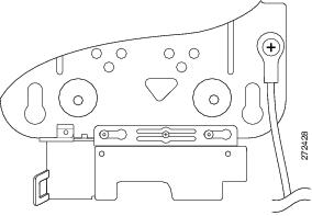
Pace 1 ![]() Use the mounting bracket equally a template to marking the locations of the mounting holes on the bracket. Figure 7 shows details of the mounting bracket.
Use the mounting bracket equally a template to marking the locations of the mounting holes on the bracket. Figure 7 shows details of the mounting bracket.

Caution ![]() Be sure to mark all four locations. To ensure a condom and secure installation, brand sure you are using adequate fasteners and mount the access point using no less than four fasteners.
Be sure to mark all four locations. To ensure a condom and secure installation, brand sure you are using adequate fasteners and mount the access point using no less than four fasteners.
Caution ![]() Do non apply plastic wall anchors or the keyhole slots on the mounting bracket for ceiling installations. When mounting the access point on a hard ceiling, utilise four fasteners capable of maintaining a minimum pullout force of 20 lbs (9 kg).
Do non apply plastic wall anchors or the keyhole slots on the mounting bracket for ceiling installations. When mounting the access point on a hard ceiling, utilise four fasteners capable of maintaining a minimum pullout force of 20 lbs (9 kg).
Figure 7 Universal Mounting Bracket Details
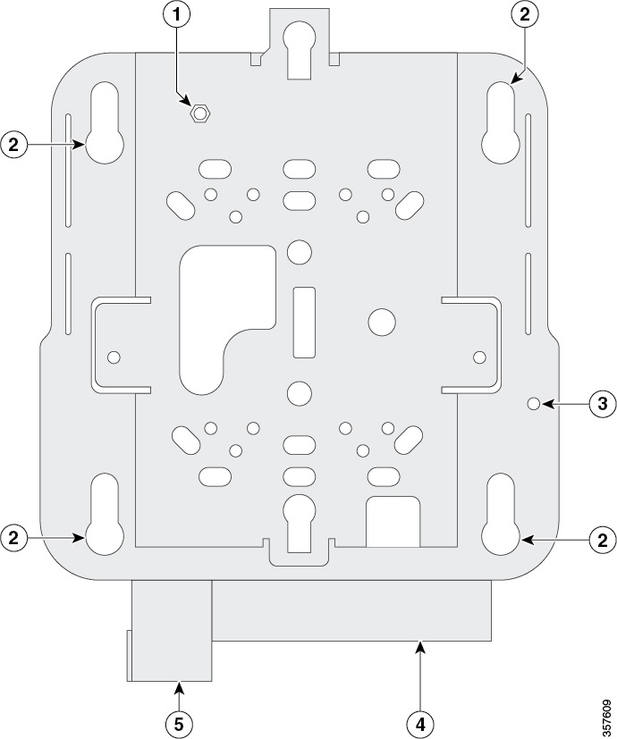
| i | Subclass locking post (used when attaching the subclass to a previously mounted bracket) | four | Cablevision access cover |
| 2 | Access point mounting keyholes | 5 | Security hasp |
| 3 | Grounding post |
Step 2 ![]() Employ a #29 drill (0.1360-in. [3.4772 mm]) bit to drill a pilot hole at the mounting hole locations you marked.
Employ a #29 drill (0.1360-in. [3.4772 mm]) bit to drill a pilot hole at the mounting hole locations you marked.
Note ![]() The pilot hole size varies co-ordinate to the material and thickness yous are fastening. Cisco recommends that you test the material to determine the platonic hole size for your mounting application.
The pilot hole size varies co-ordinate to the material and thickness yous are fastening. Cisco recommends that you test the material to determine the platonic hole size for your mounting application.
Pace 3 ![]() (Optional) Drill or cutting a cablevision access hole near and below the location of the mounting subclass cable access comprehend big plenty for the Ethernet cable, edifice ground wire, and power cables.
(Optional) Drill or cutting a cablevision access hole near and below the location of the mounting subclass cable access comprehend big plenty for the Ethernet cable, edifice ground wire, and power cables.
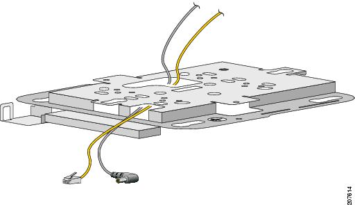
Step 4 ![]() Pull approximately 9 inches of cable through the hole. Route the Ethernet and power cables through the bracket before you attach the bracket to the ceiling or wall. Route the cables through the main cablevision access hole and then through the smaller access pigsty as shown in Figure 8.
Pull approximately 9 inches of cable through the hole. Route the Ethernet and power cables through the bracket before you attach the bracket to the ceiling or wall. Route the cables through the main cablevision access hole and then through the smaller access pigsty as shown in Figure 8.
Figure eight Routing the Ethernet and Power Cables
Footstep 5 ![]() (Optional) Use the ground screw to attach the building ground wire to the mounting bracket. Run into the "Grounding an Admission Point" section for general grounding instructions.
(Optional) Use the ground screw to attach the building ground wire to the mounting bracket. Run into the "Grounding an Admission Point" section for general grounding instructions.
Stride half dozen ![]() Position the mounting bracket mounting holes (with indents down) over the pilot holes.
Position the mounting bracket mounting holes (with indents down) over the pilot holes.
Stride seven ![]() Insert a fastener into each mounting hole and tighten.
Insert a fastener into each mounting hole and tighten.
Step 8 ![]() Connect the Ethernet and ability cables to the access point.
Connect the Ethernet and ability cables to the access point.
Stride 9 ![]() Marshal the admission bespeak feet with the large part of the keyhole mounting slots on the mounting plate. When positioned correctly, the cablevision admission cover will fit inside the access point connector bay.
Marshal the admission bespeak feet with the large part of the keyhole mounting slots on the mounting plate. When positioned correctly, the cablevision admission cover will fit inside the access point connector bay.
Step 10 ![]() Gently slide the access point onto the mounting bracket keyhole slots until it clicks into place.
Gently slide the access point onto the mounting bracket keyhole slots until it clicks into place.
Mounting an Access Point to a Network or Electrical Box
Follow these steps to mount an access point to a network box or an electrical box.
Step 1 ![]() Position the universal mounting bracket (AIR-AP-Bracket-2) over the existing network or electrical box and align the bracket mounting holes with the box holes.
Position the universal mounting bracket (AIR-AP-Bracket-2) over the existing network or electrical box and align the bracket mounting holes with the box holes.
Step two ![]() Hold the mounting bracket in place and insert a 6 x 32 x 1/4-in pan head screw into each of the mounting holes and tighten.
Hold the mounting bracket in place and insert a 6 x 32 x 1/4-in pan head screw into each of the mounting holes and tighten.
Step iii ![]() Pull approximately ix inches of Ethernet and ability cable through the hole. Road the cables through the bracket earlier you lot attach the bracket to the ceiling. Route the cables through the main cable access hole and and then through the smaller admission hole equally shown in Figure 8.
Pull approximately ix inches of Ethernet and ability cable through the hole. Road the cables through the bracket earlier you lot attach the bracket to the ceiling. Route the cables through the main cable access hole and and then through the smaller admission hole equally shown in Figure 8.
Footstep 4 ![]() (Optional) Use the basis spiral to adhere the edifice basis wire to the mounting subclass. See the "Grounding an Access Signal" section for full general grounding instructions.
(Optional) Use the basis spiral to adhere the edifice basis wire to the mounting subclass. See the "Grounding an Access Signal" section for full general grounding instructions.
Step v ![]() Connect the Ethernet and power cables to the admission point.
Connect the Ethernet and power cables to the admission point.
Step half-dozen ![]() Align the admission point feet over the keyhole mounting slots on the optional mounting bracket.
Align the admission point feet over the keyhole mounting slots on the optional mounting bracket.
Step vii ![]() Slide the access point onto the optional mounting subclass until it clicks into place.
Slide the access point onto the optional mounting subclass until it clicks into place.
Mounting an Access Point Above a Suspended Ceiling
Using third-party accessories (not offered by Cisco) you can mount an access betoken above a suspended ceiling. The universal mounting subclass (AIR-AP-Subclass-2) supports a T-bar box hanger such as the Erico Caddy 512A or the Cooper B-Line BA50a. The box hanger should be oriented just above the top surface of a ceiling tile. If your ceiling uses peculiarly thick tiles, you might demand to modify the tile to allow room for the admission point or use a box hanger that allows you to adjust the peak of the access betoken, such as the Cooper B-Line BA50A.
Note ![]() Install access points above ceiling tiles but when mounting below the ceiling is not an choice. Mounting access points higher up the ceiling can interfere with advanced wireless LAN features that depend on uniform coverage, such every bit voice and location.
Install access points above ceiling tiles but when mounting below the ceiling is not an choice. Mounting access points higher up the ceiling can interfere with advanced wireless LAN features that depend on uniform coverage, such every bit voice and location.
Follow these steps to mount the access bespeak above a suspended ceiling. Effigy 9 shows the completed installation.
Figure nine T-Bar Filigree Mounting Bracket Parts
| 1 | Suspended ceiling T-rail | 4 | Mounting bracket |
| ii | Box hanger | v | Access indicate |
| 3 | Box hanger clip | 6 | T-rail clip |
Step 1 ![]() Remove a ceiling tile next to the mounting location.
Remove a ceiling tile next to the mounting location.
Step two ![]() Fasten the access bespeak mounting bracket to the box hanger using the clip or screws provided with the box hanger kit.
Fasten the access bespeak mounting bracket to the box hanger using the clip or screws provided with the box hanger kit.
Step 3 ![]() Pull approximately ix inches of Ethernet and power cable through the mounting bracket. Route the cables through the main cable access hole and so through the smaller access pigsty every bit shown in Figure 8.
Pull approximately ix inches of Ethernet and power cable through the mounting bracket. Route the cables through the main cable access hole and so through the smaller access pigsty every bit shown in Figure 8.
Step 4 ![]() Connect the Ethernet and ability cables to the access signal.
Connect the Ethernet and ability cables to the access signal.
Step five ![]() Align the access point feet over the keyhole mounting slots on the mounting bracket.
Align the access point feet over the keyhole mounting slots on the mounting bracket.
Step half dozen ![]() Slide the access point onto the mounting bracket until it clicks into place.
Slide the access point onto the mounting bracket until it clicks into place.
Step seven ![]() Attach the T-rail clips on each end of the T-bar box hanger to the ceiling rails. Make sure the clips are deeply attached to the T-track.
Attach the T-rail clips on each end of the T-bar box hanger to the ceiling rails. Make sure the clips are deeply attached to the T-track.
Step 8 ![]() Supercede the ceiling tile.
Supercede the ceiling tile.
Grounding an Access Point
Grounding is not always required for indoor installations because Cisco Aironet access points are classified as depression-voltage devices and exercise not comprise internal power supplies. We recommend that you bank check your local and national electric codes to see if grounding is a requirement.
Although grounding is not mandatory for indoor admission points, it is required in certain scenarios. It has been observed that an ungrounded indoor access bespeak that is mounted as well close to an electromagnetic source of interference (such as a fluorescent light that is on) may reboot suddenly or suffer hardware impairment. This occurs even if the indoor AP is in close proximity to the electromagnetic source of interference, and not touching the source. Grounding the respective admission indicate or the mounting bracket helps forbid this upshot from occurring. We recommend that a certified electrical technician verify whether your installation requires grounding.
If grounding is required in your surface area or you wish to ground your access point, follow these steps.
Step 1 ![]() Detect a suitable building grounding point equally close to the admission betoken as possible.
Detect a suitable building grounding point equally close to the admission betoken as possible.
Step ii ![]() Connect a user-supplied ground wire to the building grounding point. The wire should exist a minimum of #14AWG assuming a excursion length of 25 ft (xxx.5 cm). Consult your local electrical codes for additional information.
Connect a user-supplied ground wire to the building grounding point. The wire should exist a minimum of #14AWG assuming a excursion length of 25 ft (xxx.5 cm). Consult your local electrical codes for additional information.
Step 3 ![]() Route the ground wire to the access point.
Route the ground wire to the access point.
Stride 4 ![]() Adhere the wire to a suitable grounding O-band lug.
Adhere the wire to a suitable grounding O-band lug.
Step v ![]() Crimp or solder the wire to the lug.
Crimp or solder the wire to the lug.
Footstep 6 ![]() Insert the grounding post screw into the O-ring lug and install information technology on the mounting bracket equally shown in Figure ten.
Insert the grounding post screw into the O-ring lug and install information technology on the mounting bracket equally shown in Figure ten.
Figure x Installing the O-Band Lug to the Grounding Post
Footstep 7 ![]() Use a Phillips screwdriver to tighten the ground screw.
Use a Phillips screwdriver to tighten the ground screw.
Securing an Admission Bespeak
There are 2 means to secure your admission signal:
- Attach it to an immovable object with a security cable.
- Lock information technology to the mounting plate with a padlock.
Using a Security Cable
You can secure the admission betoken past installing a standard security cablevision (such as the Kensington Notebook MicroSaver, model number 64068) into the access betoken security cable slot as shown in Effigy 11.
Effigy 11 Security Cablevision Details
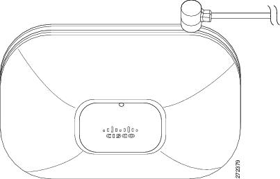
The security cable tin be used with whatever of the mounting methods described in this guide.
Follow these steps to install the security cablevision.
Pace 1 ![]() Loop the security cable around a nearby immovable object.
Loop the security cable around a nearby immovable object.
Step ii ![]() Insert the key into the security cable lock.
Insert the key into the security cable lock.
Step 3 ![]() Insert the security cable latch into the security cable slot on the access indicate.
Insert the security cable latch into the security cable slot on the access indicate.
Footstep 4 ![]() Rotate the fundamental correct or left to secure the security cablevision lock to the access point.
Rotate the fundamental correct or left to secure the security cablevision lock to the access point.
Step five ![]() Remove the cardinal.
Remove the cardinal.
Securing the Access Point to the Mounting Plate
Use the security hasp on the adapter cablevision access encompass and a padlock (that you provide) to secure your access bespeak to the mounting plate. Compatible padlocks are Chief Lock models 120T or 121T. The cable admission cover on the mounting bracket covers the cablevision bay area (including the ability port, Ethernet port, console port, and the mode push button) to prevent the installation or removal of the cables or the activation of the mode button.
Follow these instructions to install the padlock:
Step i ![]() With the access point installed on the mounting bracket, insert a padlock into the security hasp.
With the access point installed on the mounting bracket, insert a padlock into the security hasp.
Annotation ![]() If your access point is mounted to a difficult ceiling, the clearance betwixt the mounting bracket and the ceiling is small. Piece of work slowly using both hands to position and secure the lock into the mounting bracket hasp.
If your access point is mounted to a difficult ceiling, the clearance betwixt the mounting bracket and the ceiling is small. Piece of work slowly using both hands to position and secure the lock into the mounting bracket hasp.
Footstep 2 ![]() Rotate the lock clockwise and align the bail with the lock trunk.
Rotate the lock clockwise and align the bail with the lock trunk.
Step 3 ![]() Grasp the lock and button it into the bail to lock the lock. Meet Figure 12.
Grasp the lock and button it into the bail to lock the lock. Meet Figure 12.
Figure 12 Inserting the Padlock into the Security Hasp
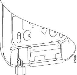
Step four ![]() Rotate the padlock into the padlock area. See Figure 13.
Rotate the padlock into the padlock area. See Figure 13.
Effigy xiii Rotating the Padlock into the Padlock Area
Obtaining Documentation and Submitting a Service Asking
For information on obtaining documentation, submitting a service request, and gathering boosted information, meet the monthly What'due south New in Cisco Product Documentation, which as well lists all new and revised Cisco technical documentation, at:
http://world wide web.cisco.com/en/U.s./docs/general/whatsnew/whatsnew.html
Subscribe to the What's New in Cisco Product Documentation as a Really Simple Syndication (RSS) feed and ready content to be delivered directly to your desktop using a reader application. The RSS feeds are a free service and Cisco currently supports RSS Version ii.0.
Cisco and the Cisco Logo are trademarks of Cisco Systems, Inc. and/or its affiliates in the U.S. and other countries. A listing of Cisco'southward trademarks can be establish at www.cisco.com/become/trademarks. 3rd party trademarks mentioned are the property of their respective owners. The use of the discussion partner does non imply a partnership relationship between Cisco and whatever other company. (1005R)
© 2019 Cisco Systems, Inc. All rights reserved.

Cisco Air Lap1142n E K9 Anleitung,
Source: https://www.cisco.com/c/en/us/td/docs/wireless/access_point/mounting/guide/apmount.html
Posted by: delgadoexper1992.blogspot.com
0 Response to "Cisco Air Lap1142n E K9 Anleitung"
Post a Comment